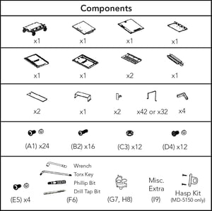
What's Included
Instructions to Assemble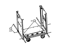
-
Attach both side panels to the bottom of the cart. Position the studs in the side panel into the tabs in the base and hand tighten 2 nuts (C3) on each side with the 8mm wrench (F6). Do not use a power tool to tighten nuts on any step. Use 3 screws and 3 washers (A1) in each corner.
-
 Install the tray lid for the bottom shelf using one screw and one washer (A1) on each side.
 -
 Install the upper tray. Position over the studs in the side panels and hand tighten 4 nuts (C3) with the 8mm box wrench (F6).
 -
 Install the tray lid for the top shelf using one screw and one washer (A1) on each side.
 -
 Align the top panel of the cart with the side panels and position it in place. Do not secure the top during this step. The top will be secured in step 19.
 -
 Locate the holes on each corner of the top panel for the gray rubber bumpers. With the included drill tap bit (F6), drill through the holes to ensure the screw goes in securely. Place a bumper to each corner of the cart’s top and secure in place using 4 screws (B2). The bumpers have a top and bottom side to them. The side with the circle marks should be facing down. To allow for the cart to be squared in a later step, do not fully tighten the screws during this step.
  Attach the rear center support to the top and bottom panels of the cart using 2 screws with 2 washers (A1) on each end. To allow for the cart to be squared in a later step, do not fully tighten the screws during this step.
-
 OPTIONAL- If installing the charging cables at the same time as the cart assembly, installing after step 7 provides the most unimpeded workflow. Don’t worry, you can still easily install the charging cables after the cart is fully assembled if needed.
 -
 Attach the door to the hinge on the right side panel with 4 screws and 4 washers (E5). Insert the Torx key (F6) through one of the screw holes on the hinge and door to help hold it in place. Remove the key once the first 3 screws are inserted. Insert the 4th screw while holding the door. Check that the door is square and opens/closes without striking the frame.
 -
 Attach the brackets for wrapping the power cable to the cart’s left side panel using 1 screw and washer (A1) on each.
 -
 Attach the mounting plate for the Intelligent Charging System to the top of the cart using 2 screws with washers (D4).
 -
 Align the openings on the bottom of the Intelligent Charging System with the clips on the mounting bracket and apply pressure to clip it into place.
 -
 Find the plug end of the main power cable. Route it down the opening in the top of the cart and out of the opening on the left side of the cart. Plug the socket end of the cable into the back of the Intelligent Charging System. Pull any excess cable out of the cart and wrap it around the brackets installed in step 9.
 -
 Route the 4 power strip cables through the hole in the top of the cart. Looking at the cart from the back side, plug the power strip that is farthest to the right in the cart into the outlet in the back of the Intelligent Charging System that is labeled “1” and repeat with the following cables in order.
 -
 Install the cable cover over the back of the Intelligent Charging System using 2 screws with washers (D4). Use the Torx key (F6) to tighten the screws. Do not use a power tool as it will leave scratches on the cable cover.
 -
 Check the cart square by placing a rafter square in the bottom corner of the door frame or use the door as a guide. Check that the gap around the door edges to make sure that it is even and the door has smooth operation. Fully tighten screws on the left and right sides of the cart.
 -
 Attach each of the rear access panels to the cart using 4 short screws with plastic washers (D4).To allow for the cart to be squared in a later step, do not fully tighten the screws during this step. Do not use a power tool.
 -
 Check the cart square by placing a rafter square in the bottom corner of the door frame or use the door as a guide. Check that the gap around the door edges to make sure that it is even and the door has smooth operation. Fully tighten screws on the front and rear sides of the cart.
 -
 Secure the top of the cart using 4 nuts (C3).
 -
 If the charging cables were not installed in step 8, install the cable management clips (G7, H8) underneath each tray for later use. See page 6 for further instructions on cable clips. Secure each tray lid shut with one short screw with a silver washer (A1).
 -
 MD-5150 Model Only- Locate the two screw holes on the inside of the front door between the locking hardware. With the swing handle in the open position, align the hasp hardware with the two screw holes on the front side of the handle. Insert the two included screws from the inside of the door to secure. Padlocks are not included.
 -
Insert the metal device dividers into the trays. See page 8 for instructions on inserting the dividers.
-
 To check that the charging system is properly connected, plug the cart into a working outlet. The Intelligent Charging System should make a brief “beep” sound, the firmware version should display in the LCD window, and a blue light will illuminate to indicate the system is receiving power.